Edge computing is being developed to satisfy the low-delay requirements of cyber-physical systems (CPS). The network edge consists of heterogeneous and frequently resource-constrained hardware operating under real-time requirements. Furthermore, the need to write and support fast and portable code, often with low operational footprints, is critical in CPSs.
A promising solution is WebAssembly, which has been extracted from the browser world, standardised, and in some cases, edge-enhanced. Through a time-critical welding application, this paper quantifies the responsiveness of a CPS system running WebAssembly and contrasts it with the same system using native binaries. We show the performance running WebAssembly is slightly lower, however, is relatively agnostic to its placement. Industrial, robotic and networks requirements are given, with our conclusions conditioned on a particularly stringent 100ms latency.
Introduction
Several high-level languages can be compiled to WebAssembly bytecode; Python, C++, Rust, Go and more, see [wasm_langs]. WebAssembly (WASM) was initially developed to provide a lightweight and performant compilation target for Web-based applications [Haas2017]. We postulate it fulfils attributes needed for CPS systems: responsiveness, portability, and openness, see [wikström2020ever]. Networked CPS applications often cross multiple areas: robotics, operating systems, networking plus performance analysis.
We focus on i) task responsiveness, ii) placement of WebAssembly applications. Next is requirements section. Requirements and a key concept Responsiveness. Since robotic movement is our use case, we consider this in paragraph [Robotic_application] including a real task and how it is done. Placement is in Placement. WebAssembly is briefly explained in sec. wasm and importantly, its optimisation in [wasm_optimisation]. The experimental design is in paragraph [exp_design]. Quantitative results are in sec. [results]. The discussion [Discussion] we see as particularly important, from a robotics PoV. Related and future works in [Related_work] and [Future_work]. We round off with conclusions in paragraph [Conclusions].
A solution
Edge computing is being developed to satisfy the low-delay requirements of cyber-physical systems (CPS). The network edge consists of heterogeneous and frequently resource-constrained hardware operating under real-time requirements. Furthermore, the need to write and support fast and portable code, often with low operational footprints, is critical in CPSs. A promising solution is WebAssembly, which has been extracted from the browser world, standardised, and in some cases, edge-enhanced. Through a time-critical welding application, this paper quantifies the responsiveness of a CPS system running WebAssembly and contrasts it with the same system using native binaries. We show the performance running WebAssembly is slightly lower, however, is relatively agnostic to its placement. Industrial, robotic & networks requirements are given, with our conclusions conditioned on a particularly stringent 100ms latency.
A use-case
Several high-level languages can be compiled to WebAssembly bytecode; Python, C++, Rust, Go and more, see . WebAssembly (Wasm) was initially developed to provide a lightweight and performant compilation target for Web-based applications . We postulate it fulfils attributes needed for CPS systems: responsiveness, portability, and openness, see . Networked CPS applications often cross multiple areas: robotics, operating systems, networking plus performance analysis, the Figure below.

A networked factory. Shown is a robot CPS application. Dark blue blocks represent network operations, whilst orange blocks represent robotics. Red-green-blue boxes indicate deployment locations for WASM and green possible edge locations. Note the internals of an industrial robot.
A networked factory. Shown is a robot CPS application. Dark blue blocks represent network operations, whilst orange blocks represent robotics. Red-green-blue prompt-like boxes indicate deployment locations for WASM and green possible edge locations. Note the internals of an industrial robot.
We focus on i) task responsiveness, ii) placement of WebAssembly applications. Next is a requirements sec. and a key concept. Since robotic movement is our use case, we consider this below including a real task and how it is done. Placement WebAssembly is briefly explained in sec. and importantly, its optimisation. The experimental design is in paragraph [experimental design]. Quantitative results are paragraph [results]. The discussion we see as particularly important, from a robotics PoV. Related & future works similarly named sections . We round off with conclusions (obviously).
The Requirements

Selected latency requirements for Industry 4.0, Industrial Robotics and 3GPP Networking standards.
Task Responsiveness

A time layer illustration. Vertically downwards, the CPS task time, the application responsiveness, industrial robot control, the WASM runtime, the WASI ‘system’ access, the network latency, the path delay and smallest of all, light propagation. The italicised nouns indicate a time ‘budget’ associated to each layer. Horizontally, the elapsed time for each to complete (not to scale).
We prefer the term responsiveness, over latency, to emphasise the interaction of CPS applications. Data is sent & received, often iteratively (implying RTTs) in round trip iterations, often regulated by control loops. The work below illustrates how an operational CPS application is better suited to using responsiveness than purely delay / latency. Note cascaded or multiple interactions are needed to control industrial robot arms due to the tasks the robotic arms are tasked to undertake.
The Application & WASM Runtimes
Since WASM can run in theory on many architectures, its placement options are an attractive property to consider, shown in the factory Figure.
Red (cloud / core), the control software at the core cloud where there is compute, local testing, local development, and central deployment, using Kubernetes or Ansible. Latency from the application and runtime are drawbacks as well as components being hosted off-prem leading to trust or unwanted lock-in and losing the ability to have fine-grained control over performance.
Green (near / far edge), the two options are the network edge and on-prem. The network edge potentially offers adequate latencies, collaborations with OEMs and operators and offloading where additional compute/backup or indeed easier 3rd party development. In a larger setting, and the application + runtime shared across many robot cells, software deployment might be more rapid. The near edge, or on-prem, may suit the robotics owner, offer lower latency, but still be under the control of the company / factory. Industry 4.0-like solutions tend to promote deployments close(r) the device.
Blue (near / at device), place control software ‘on’ the robot providing the lowest possible latency, note on the actual device, this is rarely done in an industrial setting, although is common in hobbyist robot setups. Leveraging existing compute would leave this option highly resource constrained or need compute power at every robot cell which would be expensive.
A Robotics use case : Sheet Welding
Our chosen application is a robotic arm connected to the Edge-Internet-Cloud. The task is to weld a metal segment, a common off-the-shelf industrial task. The components are i) a data broker, ii) data manipulation, iii) communications, iv) a robot cell which compromises the v) robot, vi) a tool and a vii) programmable logic controller (PLC). Box 5 within the factory figure. A WASM-enabled CPS-controlled robot application in this case would be:
CPS application = Robot application + a WASM runtime.
The software application in questions loads a robot cell digital twin and validates the proposed program before running it. The procedure is a two-step one:
Input
- The motion path (with targets)
- The speed constraints
- The acceleration constraints
Compute
- The inverse kinematics (IK) of the robot at every target to know where each joint should be
- The IK every millimetre along a metal piece
The positions, speeds and accelerations and positions for every joint along the whole path using programmed and mechanical constraints of the robot
First, forward kinematics determines the end arm position given the joint angles, whilst inverse kinematics finds the joint angles given an end effector position (the inverse). It iteratively adjusts the joint angles to minimise the difference between the actual and desired end position, see . More on the IK workload wrt. to wasm in Section
Webassembly (WASM)
The ecosystem
The top five WebAssembly applications are web development, serverless, containerisation, plugins and IoT. Nearly all are relevant to a CPS deployment . A WASM module contains the application code as well as a specification on how much memory the code needs, type declarations, and externally callable functions in the module. A WASM runtime is a bytecode interpreter that executes the WebAssembly code. A vanilla WASM runtime executes modules in a secure sandbox without access to system services and networking.
WASI & networking
One of the criticisms of WebAssembly is the lack of networking in the core specification. Therefore the WebAssembly System Interface (WASI) provides a mechanism to communicate using system calls and sockets. The API breaks out of the WASM sandbox and accesses host system resources, sockets and the file system, see and . This is done by an Application Binary Interface plus a Application Programming Interface and uses WASM to call POSIX-compliant kernel system calls in a platform independent way via a foreign function interface (FFI). Note, if WASI-like extensions are not used, then any compiled WASM should execute on any runtime.
2 Runtimes
Of the 20 active frameworks listed on Github, we selected just one shown in the Table below. XXX is supported by the Bytecode Alliance and is the most widely used default general purpose runtime, focusing on standards and stability whilst also offering good JiT performance, using the Cranelift JiT from Lucet.
| WASM + version | Language support | Framework | JiT | AoT | System Runtime |
| WASMtime 5.0 | C, C++, Rust, | Cranelift | Y | Y | WASI |
| WASMer 3.3 |
Selected WASM runtime & features. C, C#, C++, Rust, Python and Go are indicated. Prop=proprietary. Frameworks C=Cranelift and L=llvm toolchain. JiT=Just in Time compilation, AoT=Ahead of Time compilation.
CODE GENERATION & OPTIMISATION
WASM uses Just in (JiT) and Ahead of (AoT) time compilation. The main difference between the two is when the code is compiled. With JiT compilation, the code is compiled at runtime, just before it is executed. This allows the code to be optimised for the specific environment in which it is running. JiT compilation is typically used in interpreted languages, Python, or in virtual machines, Java, .NET to name two. Whereas in AoT compilation the code is compiled before it is executed. This means that the code is converted into machine code that can be directly executed on the CPU. AoT compilation is typically used in systems that have limited resources, such as embedded systems and mobile devices, as it can lead to faster execution and lower memory usage. However, AoT compilation usually result in larger binary files and less flexibility to adapt to changing environment. Comparing, JiT compilation is more flexible, adaptable and can lead to better performance but requires more resources at runtime. AoT compilation, however, is less flexible but can lead to better performance with less runtime resource usage.
Experimental setup
Influenced by Jain’s classic “The Art of Computer Performance” textbook, we have a single test hypothesis for success (or not). It is constructed to test the performance-delay requirements and by implication, the runtime placement. We show the results as the simplest form first, namely, time-, -, synthetic-real workloads.
| Name | Symbol | Formulation |
| Null | H_0 | Deploying WASM adds more than 110% of the delay of the native binary E2E delay. |
| Alternative | H_1 | Deploying WebAssembly does not add more than 110% of the non-WASM latency. |
Working hypothesis of this work. 10% additional delay is a value given i) the improvement in WASM runtimes , and on the other hand, ii) industrial requirements, section.
< g r a p h i c s >
The test environment. Light blue: our wide-area network, Dark blue: our local-area equivalent. Solid lines show network measurement points, whilst dashed lines delineate the WASM runtimes. The LAN emulates the WAN connection using FreeBSD’s DummyNet on an Odroid UX4.
Results
The presentation of the results is to show the narrowest scope first, i.e. the time taken for wasmtime to execute, then the WASM system call (or WASI) then the network delays and finally some figures from a real robotics application.
Component Evaluation Evaluation tools
WASM runtime UNIX CLI
WASI library Network measurements
Responsiveness App. req. (Table )
Placement Network simulation (emulation)
Robotics Requirements (Table ) Industrial task timings
Being at the juncture of different disciplines we break down the results into the sections and tools above.
In order to capture the end-to-end latencies in a simple manner, i.e. no GPS synchronised clocks, we used a local setup (with an emulated WAN) as well as the command line and Wireshark application at multiple points see Figure . In parallel we used the tool, a mashup tool for quantifying network delays.
Standalone WASM latencies
The UNIX environment provides the command, with options. It executes and times the specified utility. After the utility finishes, writes to standard error i) the total time elapsed, ii) the time used to execute the utility process and iii) the time consumed by system overhead in seconds. Figures quoted in this paper are derived from , but are similar to the system field of the simpler.
Standalone whisker plot showing 15 repeated runs of native binaries + executing a Fibonacci sequence generation. Time shown in milliseconds on the Y-axis. Version 5.0 of was used. The Figure shows running simple wasm code on system with lower than 5% load. Note, a Python ‘equivalent’ consumed over 2 seconds for the same task which is ×54, native, ×18, -not optimised, and ×24, -optimised, times slower than those shown in Figure .
Standalone code running on three different hardware platforms. They are chosen to represent typical compute and memory in an Cloud-edge CPS. Times are shown in milliseconds.
E2E network delays, at the cloud, and average compute times for native binaries and an optimised WASM runtime (). A 100ms requirement given by robotics polling intervals is the horizontal black line. Green blocks estimate extra protocol delays, present, but not directly measured in this work.
Measuring & estimating networking latencies
For the networking we start with from a cloud server back to a connected device. Two examples of Cloud-Edge-Device were used (Frankfurt-Stockholm and Luleå-Stockholm) with similar timings. The worst case was chosen with delays of 36.2 ± 1.9ms, see Table . Given the polling time of a robotics application is approximately 100ms, we need just over a third for the networking latency. Note this is the ICMP time and protocol delays using gRPC will be higher, therefore a margin is included in green, in Figure X.
(Semi) Real robotics
A synthetic workload
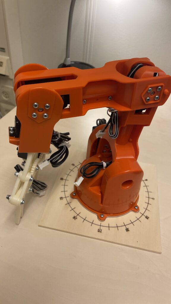
To generate a realistic task we designed a movement using the Unified Robot Description Format (URDF) markup. It is an XML-based file format used to describe the physical characteristics and properties of robots. A visualisation is shown in Figure X.
Software robot arm, used for the inverse kinematics workload.
Once the URDF is done, a Rust application [https://docs.rs/k/latest/k/] was used to read specification, calculate the inverse kinematics, and instruct the (software) arm to move. Recall, the test environment in Figure , dark blue upper rightmost functional block. Note, our purpose is to use the wasm IK code as a representative workload, essentially:
The times needed for this URDF move on a RPI4 in were 114 ± 4 ms. This is compared to 11.8 ± 2.3 ms in native mode, ×9 faster. The same code on WSL2 needs 24.3 ± 0.9 ms & natively, 1.8 ± 0.2 ms, ×13 faster. Summarising, a RPI4 would not work as an edge node with our 100ms requirement, a faster machine can, therefore future work is looking at faster SBCs, such as an Odroid UX4.
Task → URDF → Rust → wasm → IK → workload → timings.
Real world welding tasks
Not surprisingly, the real world is significantly more complex than presented hitherto. Companies use proprietary languages and frameworks, and they often have to deal with a number of deployment configurations. Not uncommon is developing with C# and .NET, and deploying using Windows Subsystem for Linux. Therefore, Windows users can use a full Linux environment without a VM or a dual boot machine but still deploy code in a Linux-managed robot cell, Figure . To complicate the picture further, Windows’ Webassembly is quite different from those considered in academic papers, see sec. , but underpins the following results.
A robotics task was split into Inputs and Compute in sec. Disregarding the Inputs here, which can be significant for large tasks, we move onto the Compute. Comparing native binaries with we saw ×10 slowdown using .NET6 and ×5 slowdown for .NET7. In-browser simulations were almost half of the time between .NET6 and .NET7. Using WSL2 is approximately ×1.3 slower than native Windows binaries. We didn’t quote absolute delays, as the timings were simulated.
Runtime Placement
A stacked barplot of the delays associated placing wasm furthest the device is Fig. . It corresponds to the location of the red runtime in Fig. . Clearly, more realistic evaluations of WASM deployment are needed. Figure shows a OMNET++ 6.0.1/INET 4.4. A topology as close to Figure is shown with a ‘real’ node acting as a WASM echo server. An relevant article in , online [https://www.brianlinkletter.com/open-source-network-simulators/]. Initial results suggest placement is possible dependent on the hardware as seen previously with the PIs.
< g r a p h i c s >
OMNET++ simulation, including realistic delays of WASM-enabled nodes, derived from the socket INET4.4 implementation (shown).
Stability
CPS systems need stability. The CoV, c_v= σ/μ as a stability metric, values <1 are considered stable, more in future work.
Discussion
The discussion around being able to place apps anywhere is, can one improve the performance of the entire system? However it is pertinent to add performant software that can only run it on the (robot) edge on relatively low-powered hardware might be easily balanced out by using a slower task in the cloud. Where the bottleneck resides is a consideration, e.g. processing large amounts of data which can come from various places then having the app running next to the data source could easily outweigh the performance penalty. Performance-wise a WASM slow down is not optimal however when it represents a slowdown. Additional tasks take time & become the real issue, exemplified by the upper layers of the delay pyramid, Fig .
Related work
From 2019, measures the performance of WASM code. The work differs from ours in that the execution time in browsers is measured. The work appears in 3 guises including punny titles such as “Mind the gap”, a ;login: article & a video presentation [“Not so fast” presentation https://youtu.be/dK-8O-ajQQQ]. They also implemented a framework for emulating a UNIX kernel in browsers, , which allows comparing Wasm & native code. They found a ×1.3 performance advantage of Wasm over JavaScript, and a ×1.45–1.55 slowdown compared to native binaries using the SPEC CPU benchmark suite.
Yan et. al looked at WASM from 2021 and compared it with Javascript across different browser environments, a clear difference to our work . They found that JiT optimisations were mostly ineffective for WebAssembly, and that the performance for both JavaScript and WebAssembly varies greatly between browser engines & platforms. They further found a significant memory overhead for WASM applications compared to the JS.
Hockley and Williamson from 2022, explored the use of as a sandboxed environment for general-purpose runtime scripting. They focused on micro-benchmarks and a macro-benchmark (both written in Rust) to compare execution times between JiT WASM execution & native execution. They used simple microbenchmarks and a Web proxy caching simulator as an example for the macrobenchmarks. They state a ×5–10 performance penalty for WASM.
Napieralla in 2020 compared WebAssembly and Docker for deployment on constrained IoT devices in terms of capabilities and performance . The work uses a number of benchmarks to compare the performance of the Wasmer runtime with both native execution and Docker containers as alternative(s). They state WASM compiled binaries take twice as long as native binaries and the startup time for a WASM runtime is ×0.1 that of a Docker container.
Future work
We are continuing this work with four additional runtimes, namely: , and . Application startup time (hot & cold), code size, and system access are all factors in deciding to which WASM environment to select. One author [https://hal-robotics.com/] produces robotic production systems based on .NET. Blazor, Microsoft’s WASM solution, and their application code is being profiled in real production systems. Light, medium & heavy synthetic workload generation+in detail profiling via call graph analysis of wasm using Rust-based tools.
Take aways
We have microbenchmarked the runtime as of Feb. 2023 in this paper. Compared to previously published work it been updated to version 5.0 and has not previously been published in peer-reviewed work. At a macrobenchmark level we have shown a WASM runtime in an E2E Cyber-Physical system, with the particular emphasis on networked systems. Variational analyses, based on a relatively simple set of requirements, taken from a robotics polling latency, shows that when optimised and deployed furthest from the device squeezes under an accepted requirement (100ms). This has been further verified by network simulations. Closer (to the device) deployments would be under the 100ms values using . That means we reject the H_0 hypothesis and accept the alternative H_1 one.
Thanks
We thank Andrew Williams & Wolfgang John of Ericsson Sweden for their comments on this work. Also CELTIC office with project ID C2019/3-2, Vinnova Sweden, project name Automation of Network edge Infrastructure and Applications with aRtificiAl intelligence (ANIARA), ID 2020-00763.
Further reading
RISE Research Dissemination, Sept. 2023, Link
4 page research paper, 2023, Link.
Master’s thesis, 2022, Link.